


FrSky Redundancy Bus-10 (RB-10)
RB-10
New product
Interface for 8 servos with redundancy for receiver and receiver battery with telemetry
1 Item
Features:
- surge protection on each channel
- option to connect two receivers and two batteries for redundancy
- 50 Hz mode for servos (20 ms period) or SBUS mode
- Integrated telemetry (voltage, overload indication)
- adjustable servo signal period
- HV Servers Support
- compact size and upgradeable firmware
Specifications:
- input voltage 4 to 8.4 V (1-2 Lipo or 4-6 NIMH)
- Number of channels: 8 PWM, 16 SBUS
- temperature range: -20 - 75 °C
- Weight: 10g
- dimensions: 63 mm × 27 mm × 10.5 mm
- overvoltage protection: 2.5 A for 10 s, 5 A immediately
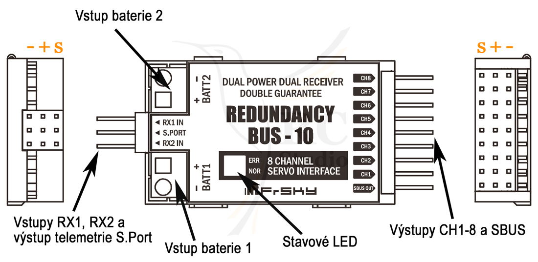
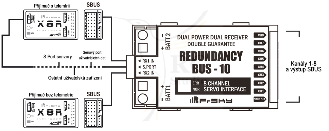
Engagement:
RB-10 does not have a voltage regulator, so you need to connect batteries or regulator that can handle your servos and receivers. The power supplies are connected to BATT1 and BATT2. You can power the RB-10 from one source (plugged into BATT1 or BATT2) or from two sources (plugged into BATT1 and BATT2). For proper operation of the protection it is important that both power supplies can be loaded with a minimum of 15 A and a peak of 40 A. Never connect more than one servo to the output. The S.Port of the RB-10 can be connected to the end of a row of sensors or use a Y cable to connect it.
If the sources have the same voltage, they are drawn from both sources. If this is not the case, it is preferably taken from a source of higher voltage and the sources are isolated from each other.
You can use any source (different cell counts, different battery types and capacity).
Never connect power to CH1-8, SBUS out, RX1 IN and RX2 IN.
 br />
br /> Surge Protection:
Each servo output including SBUS out and RX1 IN and RX2 IN has its own surge protection. Each channel retains a load of 2.5 A at25 ° C. If the load is higher than 5 A, the disconnection occurs. This information is signaled by telemetry.
Set the serv output period:
The default is 20 ms (50 Hz). It is possible to set a lower period according to the receiver, but keep in mind that analog servos or servos that are not built for this can show vibrations and higher power consumption, and can also be destroyed.button
- Link CH1 and CH2 with a jumper
- Turn on power
- Green LED flashes quickly to indicate that the process has been completed and the default 20 ms period has been changed to a 9 ms receiver sync
- Unlink jumper CH1 and CH2 and power
Check the period settings:
Connect the receiver to RX1 IN or RX2 IN and connect the power supply. If the green LED flashes quickly, it is synchronized with the receiver. If it remains lit, it is set to the default value of 20 ms.
Synchronization:
If the receiver sync is set, the PWM output is the same as the SBUS input.
If the receiver periods are different, if both receivers are started at the same time, the period will be determined by the receiver with a longer period. If the receivers are not switched on at the same time, the period according to the first started receiver is determined.
Telemetry data:
- Status information for each servo channel - disconnect
- Voltage for each battery
- Receiver Sync and Condition
| Description | Unit | |
| RB1V | battery voltage 1 | In |
| Rx1F | 0: normal state 1: Rx1 Failsafe | |
| Rx1L | 0: normal state 1: Rx1 data loss | |
| Rx2F | 0: normal state 1: Rx2 Failsafe | |
| Rx2L | 0: normal state 1: Rx2 data loss | |
| Rx1C | 0: normal state 1: Rx1 Disconnect | |
| Rx2C | 0: normal state 1: Rx2 Disconnect | |
| Rx1S | 0: normal state 1: Rx1 No signal | |
| Rx2S | 0: normal state 1: Rx2 No signal | |
| RB2V | battery voltage 2 | In |
For the new OpenTx, you can replace items 3 through 10

On all items we offer warranry 24 months.
Spare parts and battries capacity 6 months.

We provide warranty and post warranty services.